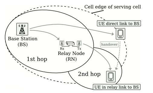
Relay Nodes have been introduced to meet the growing demand and challenging requirement for coverage extension and capacity management in a cost efficient way.
What do you mean by Relay Node here?
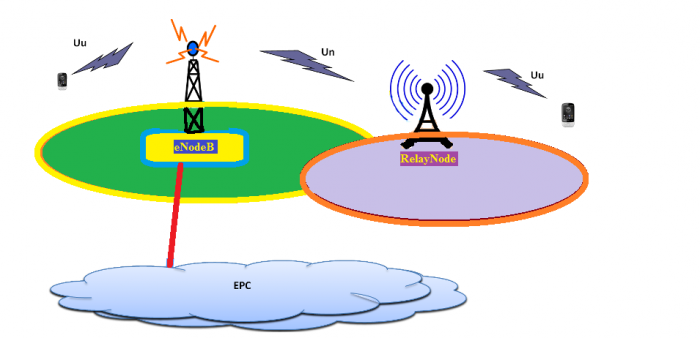
It is basically a feature of LTE-Advanced. It is relatively small nodes with low power consumptions and connect to the core network with a wireless back-haul through an evolved Node B (eNB). It enhances the data rate in the network. You can say it is a wireless eNodeB which controls it's own cell, it has it's own cell ID and includes functionalities as Radio Resource Management, Scheduling and HARQ re-transmissions.
Usually pico,femto and micro cells are consider in this domain but world wide pico or micro is under consideration for this feature because the femto cell is being controlled by owner not the service provider.
Un Interface: It is a modified version of E-UTRAN air interface Uu. Un interface is between DeNB (Donor eNodeB) and Relay Node. Donor eNB also srves its own UE as usual, in addition to sharing its radio resources for Relay Nodes.

Why was it required?
LTE technology uses MIMO-OFDM concepts to deliver high data rate. At high carrier frequency say 2.6 GHz the network has to face path loss attenuation which was the reason there was a Limitation of cell size. In addition the down tilt angle of the antenna reduce the interference in Neighboring cells which also cause the limitation of cell sizes. Due to these deployment constraints there was also a cap on the capability with LTE technology in terms of coverage and capacity. Therefore to enhance existing LTE networks by deploying full decode and forward relays the Concept of Relay Network has been advised.

Donor eNodeB:
The donor eNB (DeNB) is enhanced to provide S1 and X2 proxy functionality between the RN and other network nodes (other eNBs, MMEs and S-GWs). The S1 and X2 proxy functionality includes passing UE-dedicated S1 and X2 signalling messages as well as GTP data packets between the S1 and X2 interfaces associated with the RN and the S1 and X2 interfaces associated with other network nodes. Due to the proxy functionality, the DeNB appears as an MME (for S1-MME), an eNB (for X2) and an S-GW (for S1-U) to the RN.
Note:
- A UE is connected either to the donor eNB or a RN, but not both. In addition, the UE shall receive scheduling information and HARQ feedback from the RN and send its control channels to the RN.
- For backward compatibility, a RN appears as an LTE Rel. 8 eNB to LTE Rel. 8 UEs so that all legacy LTE Rel. 8 UEs can be served by the RN. On the other hand, the RN should appear differently than the LTE Rel. 8 eNB to LTEAdvanced UEs.
Limitations:
- Because of low transmit power, the coverage areas of the relay nodes will be small. Therefore the performance of relay deployments may be limited by load imbalances.
