top button
Flag Notify
    Connect to us
      Site Registration

Site Registration

The Cisco Three-Layer Hierarchical Model.

+2 votes
463 views

Cisco layer model consist of the following three layers.

The Core layer

The Distribution layer

The Access layer

Each layer plays a role and specific responsibilities are assigned to these three logical layers. These layers are same like the network layers of OSI reference model.

Core Layer

Core layer is know as core of network as it is on the top of the network and it is responsible to transfer heavy amount of traffic in reliable and quick manner. Objective of core layer is to speed up the network traffic as much as possible. Traffic at core layer is common for most of users and user data is transported to distribution layers which forwards requests if it is required. If core layer is affected by a failure, every user is affected on network. Fault tolerance is main thing to consider on this layer.
The main responsibility of core layer is to see heavy traffic, so speed and traffic issues are concerned at this layer. What are functions of core layer not do the following things.

Protect the network from slowing down the traffic, use of access lists, routing between different Virtual Local Area Networks (VLANs) and Packet Filtering.

Protect network from workgroup access support.

Don't expand core as network grows. Try to overcome performance issue by adding routers and prefer to upgrade devices over expansion.

However while designing core, we want to do the following things.

Design the core by using data link technologies which provides speed and redundancy like FDDI, Fast Ethernet and ATM.

Prefer to select protocols with low convergence time and fast redundant link connectivity.

Cisco Three-Layer Hierarchical Model

Distribution Layer

It is also known as workgroup layer and it is called communication point between access and core layer. Basic function of distribution layer is routing, filtering and WAN access and find out the method by which packets can access the core. This layer must find out the fastest mechanism to handle network operations like how to handling and forwarding a file to server on request. After finding best path, distribution layer forward request towards core layer and then to the right service. Policy implementation is done on distribution layer and you can exercise flexibility defining network operations.

Here are the functions which should be done at distribution layer.

Implementations of access lists for filtering interesting traffic and blocking uninteresting traffic.

Security and network policy implementation containing address translation and firewalls.

Static routing redistribution

Enabling routing between all VLANs

Defining broadcast and multicast domains

The Access Layer

User and workgroup access to network and resources is defined at access layer and this layer is also known as desktop layer.

Here are some functions of access layers.

Manage access control and policy

Create separate collision domains

Connectivity of workgroup through distribution layer

DDR (Double Data Rate) and Ethernet switching technology are mainly used in access layer with Static routing.

posted Jul 5, 2014 by Vrije Mani Upadhyay

  Promote This Article
Facebook Share Button Twitter Share Button LinkedIn Share Button


Related Articles

TCP/IP means Transmission Control Protocol and Internet Protocol. It is the network model used in the current Internet architecture as well.

Protocols are set of rules which govern every possible communication over a network. These protocols describe the movement of data between the source and destination or the internet. These protocols offer simple naming and addressing schemes.

The TCP/IP Model was developed by Department of Defence's Project Research Agency (ARPA, later DARPA) as a part of a research project of network interconnection to connect remote machines.

The features that stood out during the research, which led to making the TCP/IP reference model were:

  • Support for a flexible architecture. Adding more machines to a network was easy.
  • The network was robust, and connections remained intact untill the source and destination machines were functioning.

The overall idea was to allow one application on one computer to talk to(send data packets) another application running on different computer.


TCI/IP model consists of 4 different layers:

  1. Network Access Layer.
  2. Internet Layer.
  3. Transport Layer.
  4. Application Layer.


LEVEL 1

Network Access Layer is the first layer of the four layer TCP/IP model. Network Access Layer defines details of how data is physically sent through the network, including how bits are electrically or optically signaled by hardware devices that interface directly with a network medium, such as coaxial cable, optical fiber, or twisted pair copper wire.

The protocols included in Network Access Layer are Ethernet, Token Ring, FDDI, X.25, Frame Relay etc.

The most popular LAN architecture among those listed above is Ethernet. Ethernet uses an Access Method called CSMA/CD (Carrier Sense Multiple Access/Collision Detection) to access the media, when Ethernet operates in a shared media. An Access Method determines how a host will place data on the medium.

LEVEL 2

Internet Layer is the second layer of the four layer TCP/IP model. The position of Internet layer is between Network Access Layer and Transport layer. Internet layer pack data into data packets known as IP datagrams, which contain source and destination address (logical address or IP address) information that is used to forward the datagrams between hosts and across networks. The Internet layer is also responsible for routing of IP datagrams.

Packet switching network depends upon a connectionless internetwork layer. This layer is known as Internet layer. Its job is to allow hosts to insert packets into any network and have them to deliver independently to the destination. At the destination side data packets may appear in a different order than they were sent. It is the job of the higher layers to rearrange them in order to deliver them to proper network applications operating at the Application layer.

The main protocols included at Internet layer are IP (Internet Protocol), ICMP (Internet Control Message Protocol), ARP (Address Resolution Protocol), RARP (Reverse Address Resolution Protocol) and IGMP (Internet Group Management Protocol).

LEVEL 3

Transport Layer is the third layer of the four layer TCP/IP model. The position of the Transport layer is between Application layer and Internet layer. The purpose of Transport layer is to permit devices on the source and destination hosts to carry on a conversation. Transport layer defines the level of service and status of the connection used when transporting data.

The main protocols included at Transport layer are TCP (Transmission Control Protocol) and UDP (User Datagram Protocol).

LEVEL 4

Application layer is the top most layer of four layer TCP/IP model. Application layer is present on the top of the Transport layer. Application layer defines TCP/IP application protocols and how host programs interface with Transport layer services to use the network.

Application layer includes all the higher-level protocols like DNS (Domain Naming System), HTTP (Hypertext Transfer Protocol), Telnet, SSH, FTP (File Transfer Protocol), TFTP (Trivial File Transfer Protocol), SNMP (Simple Network Management Protocol), SMTP (Simple Mail Transfer Protocol) , DHCP (Dynamic Host Configuration Protocol), X Windows, RDP (Remote Desktop Protocol) etc.

READ MORE

The Network Access Layer of the TCP/IP model is associated with the Physical Layer (Layer 1) and the Data Link layer (Layer 2) of the OSI model. The Network Access Layer's function is to move bits (0s and 1s) over the network medium.

The OSI Physical layer is responsible for converting the frame into a stream of bits suitable for the transmission medium. The OSI Physical layer manages and synchronizes signals for the actual transmission. On the destination device, the Physical layer reassembles these signals into a data frame.

The OSI Data Link layer is again subdivided into the following two sub layers according to their function:

Media Access Control (MAC) Sublayer :— MAC sublayer provides an interface with the network adapter.

Logical Link Control (LLC) Sublayer :— LLC sublayer is responsible for error-checking functions for frames delivered also responsible for managing links between communicating devices.

Structure of an Ethernet Frame:-

The data packets from Internet Layer is moved to Network Access Layer as it moves down the TCP/IP protocol stack. There is a size limitation for Ethernet Frame. The total size of the ethernet frame must be between 64 bytes and 1,518 bytes (not including the preamble). Network Access Layer Breaks Internet Layer data (IP Datagram) into smaller chunks, if necessary, which will become the payload of ethernet frames. A Frame includes data to be transmitted and also a header and a trailer which contain information that the network adapters on the ethernet need to process the frame.

The total size of the ethernet frame must be between 64 bytes and 1,518 bytes (not including the preamble). A frame shorter than the minimum 64 bytes but with a valid CRC is called as a runt. In most cases, such frames arise from a collision. Any frame which is received and which is greater than the maximum frame size, is called a "giant". A "giant" is longer than 1518 bytes yet have a valid CRC. Both runts and giants are considered as invalid.
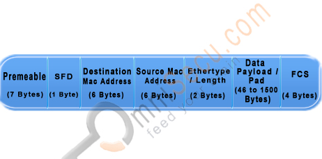
enter image description here
Figure of Structure of an Ethernet Frame

The Ethernet Frame fields are explained below

Preamble: A sequence of 56 bits having alternating 1 and 0 values that are used for synchronization. They serve to give components in the network time to detect the presence of a signal, and being reading the signal before the frame data arrives.

SFD (Start Frame Delimiter): A sequence of 8 bits having the bit configuration 10101011 that indicates the start of the frame.

Source and Destination MAC Addresses: The Source MAC Address is the MAC Address of the device this frame is coming from. The Destination MAC Address is the MAC Address of the device which is going to receive this frame. Both of these fields are 6 bytes long.

MAC address (Layer 2 addresses, physical address or hardware address) is a universally unique identifier, permanently burned in the network card. For Ethernet and Token Ring, these addresses are 48 bits, or six octets (bytes). MAC Addresses are represented in hexadecimal characters because hexadecimal format is easier for humans to read when compared with the binary format. One hexadecimal digit resembles a group of four contiguous binary bits, called a nibble. An example representation of MAC address is AA.F0.C1.E8.13.40.

Length/Type: A 2-byte (16-bit) field contains the number of bytes in the Data field or the nature of the MAC client protocol.

Data: This field contains the actual data transferred from the source device to the destination device. The maximum size of this field is 1500 bytes. If the size of this field is less than 46 bytes, then use of the subsequent "Pad" field is necessary to bring the frame size up to the minimum length.

Pad: If necessary, extra data bytes are appended in this field to bring the frame length up to its minimum size. A minimum Ethernet frame size is 64 bytes from the Destination MAC Address field through the Frame Check Sequence.

Frame Check Sequence: This field contains a 4-byte Cyclic Redundancy Check (CRC) value used for error checking. When a source device assembles a frame, it performs a Cyclic Redundancy Check (CRC) calculation on all fields in the frame except the Preamble, SFD (Start Frame Delimiter), and frame check sequence using a predetermined algorithm. The source device stores the value in this field and transmits it as part of the frame. When the frame is received by the destination device, it performs an CRC test again using the same algorithm. If the CRC value calulated at the destination device does not match the value in the FCS (Frame Check Sequence) field, the destination device will discards the frame, considering this as a transmission error.

To view the MAC Address when you are working with a Windows workstation, run cmd (Start > run > type cmd and Enter). Type the command "ipconfig /all" in the prompt and Enter. Do remember to remove double quotes.

In TCP/IP Network Access Layer lesson, you have learned the sublayers of Datalink Layer. The sublayers of Datalink layer are Media Access Control (MAC) sublayer and Logical Link Control (LLC) sublayer. You also learned about the Ethernet Frame Header, the structure of an Ethernet Frame, different fields in Ethernet Frame header, what is a runt frame and what is a giant frame.

READ MORE
...